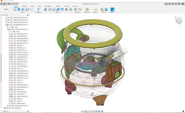
Transparent view of the internal components of the cauldron, part of the Magic Mixies kit from Moose Toys. Image courtesy of Autodesk.

Latest News
August 17, 2023
Mixing mechanical and electrical design appears to lead to some electronics magic. For instance, in an interview with The Toy Universe, Joost Poulus, Moose Toys’ chief product officer, said, “We have a big, hairy, audacious goal to be the most innovative toy company in the world and that goal is always in our sights” (“Innovation Drives Growth of Home-Grown Success Story,” December 2022). A milestone in the march toward that goal might be a plushy little creature that pops out of a cauldron in a puff of mist, part of Magic Mixies.
In 2021, the Australian toy maker first unveiled the Magic Mixies, a toy kit ready to cast its spell on the generation that has grown up on “Harry Potter” films. For the kids, the magic happens inside the cauldron. They pour some water into it, add the prepackaged dusts, a feather, and a flower, following the instructions. Then, in a swirl of smoke, a winged creature with Anime-style round eyes appears at the bottom of the pot. For the engineers, the magic happens at the intersection of mechanical and electrical design.
Another hit from Moose Toys is Mama Surprise, which teaches children to care for a guinea pig baby using a special care package. It, too, relies on integrated electronics to deliver its functions.
“Mama Surprise and Magic Mixies are two of the top-performing items in the business,” says Carl Budd, engineering manager at Moose Toys. “Both rely on electronics and have allowed us to bring new ways to play in the industry. The surprise, delight and reveal wouldn’t have been possible without the integrated electronics.”
Collaborative Magic Brew
Magic Mixies was designed in Autodesk Fusion 360, an integrated CAD, CAM and CAE suite with cloud-driven features. While people retreated indoors during the pandemic shutdown, Moose Toys engineers were busy prototyping the Magic Mixies kit. The team turned the concept into a working prototype within four months. The product was completed and the toys available in just 18 months.
“It was probably the highest complexity for a project that we ever ran entirely remotely. We did all the design reviews and collaboration remotely with our global teams,” says Budd.
Budd, who joined Moose Toys 6 years ago as a product designer, felt the company needed to move away from the siloed design workflow to speed up product development.
“It’s a fast industry. Things that are hot one year are completely old news the following year. We have to be very, very agile,” he says. “We identified the need for a better CAD package. We did a bit of a hunt but aligned on Fusion 360 pretty early on.”
According to Autodesk, Fusion 360 has now become Moose Toys’ core platform for design and manufacturing. In the Magic Mixies project, the design work and prototyping for mechanical items was a three-way collaboration among the teams in Melbourne, Los Angeles and the U.K.
“Collaboration in Fusion 360 is a massive advantage, especially given that we’re a global company. We can share our files between all our offices in Australia, Hong Kong, the U.K., the U.S. and more,” says Budd.
Mixing Mechanical and Electrical
To be in line with Magic Mixies’ play scenario, the plushy toy has to remain hidden in a chamber in the cauldron until the spell is cast and a puff of smoke is released. These functions are realized in a mix of mechanical and electrical functions, all nested inside the cauldron. It was the project that required seamless data exchange between mechanical CAD (MCAD) and electrical CAD (ECAD).
There was also tight collaboration between design and manufacturing. For designing the electronics, Budd says, “Our manufacturers will take our Eagle outputs and import into their preferred [electronic design automation] EDA software in the final stages of development. We will receive turnarounds in Gerber format, which we can easily import into Eagle for review and adjustment.”
Along with the mist that gave the toy its magical allure, creating the look and feel of the plushy creature that popped out of the pot was another design challenge.
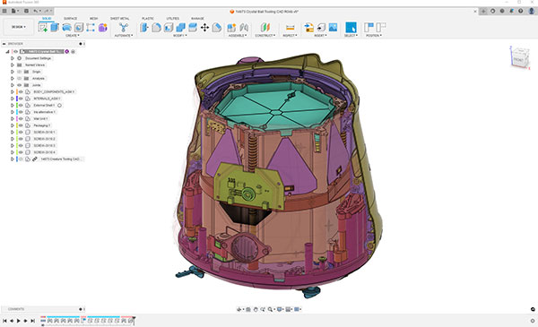
“Soft goods are an extremely difficult thing to try and model in CAD software,” Budd says. “With Fusion 360, we could get a plush look for our early internal renderings. For the Mixies Crystal Ball, we worked it out by using the form tool and applying decals and things to the surface of the form.”
Budd believes Fusion 360 was the right balance of design, simulation and visualization. “There were enough tools for the mechanical design engineers to do what we needed to do, such as simulating mechanisms and designing all the gearboxes and linkages. But it also still had the right tools for the product designers to be able to sculpt shapes,” he says. The KeyShot plug-in for Fusion 360 helped Moose Toys to produce early renderings.
The product’s size and shape, along with some moving parts, made secure packaging for shipping a challenge as well.
“For packaging, we make preliminary block models in Fusion 360, but the bulk of the design work is done using specialized packaging design software,” says Budd.
Wearable PCBs
When engineers talk about printed circuit board (PCB) design, they’re referring to the functional layout and topology of the circuit board. But when Hackster.io’s Alex Glow talks about PCB design, she’s talking about PCB boards that are designed to be accessories, where the layout is not just functional but also decorative. Her works, like her origami-inspired bouquet and her robotic owl Archimedes, are on display at Hackster.io. She maintains a directory of green electronics suppliers at bit.ly/green-ee-notion. She likes to design items that give new life to objects that would otherwise be discarded, such as used batteries and plastic pill bottles. “It’s part of my ethos,” she says.
Glow’s primary CAD software is Onshape, PTC’s cloud-hosted SaaS CAD. Onshape requires paid subscriptions for privately hosted design projects. Because Glow is willing to publish her designs publicly as open-source concepts, she’s able to use the free version of the software. She has been using the software since 2016.
For most of her projects, Glow tends to incorporate electronics, “probably because I come from the tradition of makerspaces and tinkering,” she says.
During the interview for this article, she proudly showed the latest incarnation of Arduino she’d just acquired. Lights and electrical functions powered by Arduino and Raspberry Pi are a regular feature of her design.
Tinkering With Open-Source Boards
Glow uses a mix of Tinkercad (browser-based CAD, popular with the maker community), KiCad (open-source ECAD) and PTC’s Onshape in her projects. “For an initial idea, for design, I like using Onshape. I like its sketching function,” she says.
For Glow, Onshape works well with the ECAD files she generates. The biggest hurdle is not technology but measurements. “Learn to think in millimeters,” she quips. At the scale of chips and circuitry, measuring in millimeters is more practical than measuring in fractions of inches, she explains.
Glow likes to work out her concepts with pen and paper first before moving on to CAD modeling. Some projects like the origami bouquet are so complex to model in CAD that she refined her concept in pen and paper, then used her tactile sensation and intuition to complete the job. “Making organic shapes in CAD is still a struggle,” Glow says. The discovery of sweep along a path—a CAD modeling technique to create complex surfaces—solves some of her modeling issues.
Because Glow tends to work on the electronics and the mechanical components herself, the MCAD-ECAD connection is not particularly complex. She is always aware of the dimensions needed for the electronics she needs to bring into her final assembly. On the other hand, mechanical and electrical design teams working in parallel on the same project may need a tool like the Onshape PCB Studio, allowing each to see the design changes on the other side. (For more on this topic, read “SaaS Gains Ground in ECAD” in this issue.)
The creative process is mysterious, Glow says. “Obviously, because I’m working with electronics and parametric modeling, I have to work within these constraints, but I also embrace freedom and flexibility. There’s no such thing as the proper way. I don’t feel I have to do it by other people’s so-called proper way,” says Glow.
More Autodesk Coverage
Subscribe to our FREE magazine, FREE email newsletters or both!
Latest News
About the Author
Kenneth Wong is Digital Engineering’s resident blogger and senior editor. Email him at [email protected] or share your thoughts on this article at digitaleng.news/facebook.
Follow DE

