

March 3, 2008
By Jim Barrett-Smith
 Pro/ENGINEER Routed System Designer (RSD) is a multidiscipline schematic solution that is capable ofdriving 3D design using a single, fully integrated environment. |
As every cabling harness designer knows, the design of electrical cabling systems — often exceeding 100 miles in length in large-scale aerospace and defense systems — poses enormous challenges. These are greatly exacerbated by the fact that the cabling design process involves both electrical and mechanical design. Both 2D electrical schematics and 3D solid MCAD models require very different methods and tools, and bridging the gap between these two worlds is often the most difficult part of the design process. But a new software tool, integrating the two disciplines, makes the cable design process faster and easier for engineers on both sides of the equation.
The electrical side of cabling design
On the electrical side, engineers must consider the electrical viability of the design. That means checking the voltage drops across the entire power distribution system to make sure there’s enough power at the far end of the cable to ensure safe operation of critical equipment. It also means calculating the resistance, power dissipation, and temperature rise of each conductor to be sure it will never become hot enough to melt the insulation.
Engineers also must consider the potential for electromagnetic interference (EMI) to generate spurious currents that would interfere with safe operation. For example, engineers must evaluate inrush currents that can occur when circuits are turned on and have the potential to generate EMI. They also must protect against external EMI sources such as lightning strikes and interference from other electronic equipment.
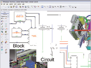
 This image of a Block Interconnect Diagram (BID) of a portion of a satellite’s electrical circuitry shows aa number of connectors providing power and data to various modules. |
Transition to the mechanical side
Engineers working on the electrical design have software tools for addressing these issues. But when it is time to move the electrical design into the physical world, typically another engineer must start from scratch and create a virtual solid model of each of the tens of thousands of wires in the electrical design, then snake them through the mechanical design, correct interferences, address critical safety issues such as temperatures and chafing, and ultimately calculate the length of each wire.
This is the point where things usually get difficult. Here, we have two designs — one electrical and one mechanical — each with tens of thousands of conductors providing both power and data to hundreds of modules. Since data entry errors are possible, and changes might be applied to either design at any time, we have to worry about how closely these two models match up, because, if the mechanical design does not accurately interpret the electrical information, the associated modules might not function correctly. So, we need to perform an exhaustive manual process of comparing and checking the data between the two disciplines, a process that usually needs to be repeated many times as the design iterates.
Another concern is that all of the calculations made on the electrical side of the design, such as voltage drops and inrush currents, depend both on the resistive and reactive characteristics of the wire, as well as the reactive load of the models being supplied. The length of the cable run can only be estimated before the cable is routed, and mechanical designers might make changes that affect the electrical side, such as replacing a pump because of supplier problems that might require different connections. So, the instant the routing is completed, the electrical design must be updated with the correct physical specifications. This requires another major job of updating the electrical schematic with the new physical specifications, verifying its accuracy, and reevaluating — and in many cases refining — the electrical design. And, of course, this needs to be repeated, at least partially, whenever the mechanical design changes.
This explains, in essence, the cabling design challenge. Using current methods and tools, the electrical and mechanical aspects of cabling design must be addressed separately in different environments. The problems arise from the interdependence between these two environments. The electrical design must be completely transferred, at least once, from the electrical world to the mechanical world, and data from the mechanical design such as wire length, must be transferred back to the electrical world. In addition, the iterative nature of engineering means that many additional data transfers must be made in both directions. Each of these manual updates consumes substantial work-hours, and is often fraught with errors.
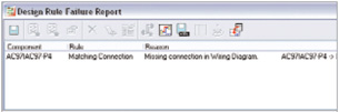 Verification Check Image provides a full suite of verification tools to ensure the Block InterconnectDiagram (BID) is accurately represented in the wiring interconnection diagram (WID). |
Bridging the gap between electrical and mechanical
Electrical and mechanical engineers have found an easy and comprehensive solution to this problem with the newest version of Pro/ENGINEER Routed Systems Designer (RSD) 7.0 from PTC.
Pro/ENGINEER RSD 7 provides a single, fully integrated environment for creating the top-level system design and electrical schematic that integrates the flow of information throughout the entire cabling design process. You create your electrical schematics in RSD, and all the connectivity information required by electromechanical designers is electronically sent via XML to automate the routing within the digital mockup.
Pro/ENGINEER RSD doesn’t just find an available path for the cabling, it finds the best possible path. And using two optional add-ons — PTC’s RSDSimulate and SMARTSymbol libraries from PTC partner Virtual Interconnect (not required with RSD) — you can even simulate the schematic from an electrical standpoint. Because designers can only assume wire and cable lengths, the analysis provided by this solution serves as a guide to the designer.
The “smart” piece happens once the schematic data has been electronically transferred to the mechanical design for routing within the digital mockup. At that point, routing information such as wire length can be extracted from the cabling design and reused for further, more accurate simulation.
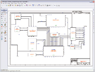
Pro/ENGINEER RSD 7.0 provides an environment to develop the block interconnection diagram (BID) that’s often used to define the top-level system design as well as the wiring interconnection diagram (WID). The BID describes the different modules at a high level and how they are to be interconnected. It provides a high-level representation of the critical requirements of the electrical design that serves as a guide to the often large team of electrical engineers responsible for the detailed design process. In the normal design flow, a single engineer or a small team creates the BID, which is then divided into sections and parceled out to a larger group of engineers who create the schematic diagram that forms the basis of the WID.
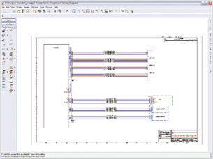 Wiring Interconnect Diagram (WID) creation is automated from the corresponding Block InterconnectDiagram (BID). |
BID linked to WID
Pro/ENGINEER RSD can also be used to create the WID that’s used to define the wiring design at the most electrically detailed level. Normally, a considerable amount of time must be spent at various stages of the design process checking the BID against the WID to ensure that all the required interconnections are made correctly between modules. The linkage between the BID and WID provided by Pro/ENGINEER RSD automates this checking process, saving a considerable amount of time and eliminating the risk of errors.
In addition, Pro/ENGINEER RSD provides an environment for schematic design that supports concurrent engineering, so that each engineer has full access to the BID, making it easy to define design rules including diameter, thickness, grouping, packing, strip lengths, terminators, etc., and enforcing these rules during the cable routing process.
Engineers can use 2D symbols from Virtual Interconnect’s SMARTSymbol library to define the electrical and mechanical aspects of the cable such as resistance, inductance, and capacitance per unit length, and voltage and current rating. Virtual Interconnect’s SMARTParts library also provides 3D geometry. These libraries seamlessly integrate with RSDSimulate, which determines voltage drops as a function of loading or current everywhere on the circuit.
Electrical schematic drives 3D routing
At a suitable point, well before the schematic is completed, you can leverage the knowledge contained within the schematic to automate the creation of harnesses within the 3D CAD assembly. This streamlines the design process by removing the tedious manual process of interpreting 2D schematic diagrams. Plus, by automating this process, you virtually eliminate inconsistencies between the electrical and mechanical designs by ensuring adherence to the schematics.
Upon importing the XML file containing the 2D electrical information into the 3D CAD model of the product, the engineer has the option of routing the cable either manually or automatically. The design rules that were defined in the electrical schematic, transferred along with the connectivity information, are used to drive both manual and automated routing. The SMARTParts library saves additional time by providing 3D CAD models of the various types of connectors that are automatically invoked based on the schematic.
When the cable routing process is completed, you can export the length of each cable run and other parameters back to the 2D RSD design environment in order to update the schematic diagram. This, in turn, makes it possible to re-run the electrical simulation with accurate cable lengths. These operations can be performed without the tedious task of manually entering data, which can be time consuming and prone to errors. Whenever a design change occurs, the new design information can easily be transferred electronically.
By bridging the gap between the electrical and mechanical disciplines, Pro/ENGINEER Routed Systems Designer 7.0 and the Virtual Interconnect libraries can dramatically reduce the time and risk of error involved in cabling design. No doubt, as products become more complex, the length of cable harnesses will continue to grow. Yet, with today’s advanced 3D design technology, the time required to design these massive harnesses will continue to become more and more compressed.
More Info:
Pro/ENGINEER RSD 7.0
PTC
Needham,MA
ptc.com
Jim Barrett-Smith is a product manager at PTC. To comment on this article, send e-mail to DE- [email protected].
Subscribe to our FREE magazine, FREE email newsletters or both!
About the Author
DE’s editors contribute news and new product announcements to Digital Engineering.
Press releases may be sent to them via [email protected].


